Vernier Caliper is a widely used precision tool for dimensional measurements in production shops, inspection facilities, R&D labs, design labs, and other applications. It can measure internal, external, and depth dimensions. Like any other instrument, its utility lies in its ability to provide accurate and precise measurements. Periodic calibration is essential to maintain confidence in its measurements. Here is a complete guide for calibrating vernier calipers. Moreover, check this complete guide to calibration of MMEs.
REFERENCE STANDARDS & EQUIPMENT REQUIRED
- Steel gauge blocks (Grade 1 or higher accuracy)
- Ring gauges (25 mm and 50 mm)
- Surface plate
- Precision pin gauge
- Thermo-hygrometer for monitoring temperature and humidity
PRELIMINARY OPERATIONS
- Environmental conditions during calibration should be maintained as follows:
- Temperature: 20°C ± 2°C
- Humidity: 35% ± 15%
- Allow the reference standards and vernier caliper to stay in lab conditions for at least 4 hours before calibration.
- Clean and deburr all critical surfaces of the vernier caliper.
- Always handle equipment, particularly gauge blocks, with gloves.
- Loosen the vernier sliding jaw thumb screw. Ensure it moves freely along the entire beam.
- Place the precision pin gauge between the caliper jaws as close as possible to the caliper beam. Observe the caliper scale and record the indication. Using the same location on the precision pin gauge, place it at the opposite end of the caliper measuring jaws. Observe the caliper scale and record the indication. The two indications must agree with each other and be within permissible tolerance limits.
*Note: Wringing is the process of sliding gauge blocks together to adhere without gaps.
CALIBRATON METHOD
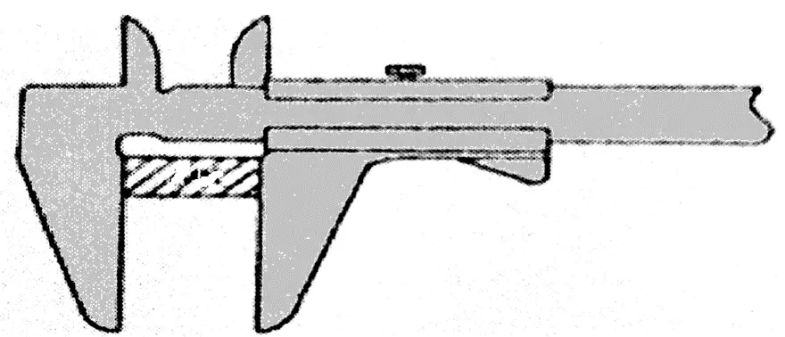
External measurement
- Determine the gauge block sizes required to obtain Caliper indication at approximately 25%, 50%, 75%, and 100% of full scale range. If any required gauge block is not available stack two or more gauge block using wringing process* to obtain the desired length. Give at least 1 hour time to stacked gauge blocks to achieve stable temperature in lab conditions. For length above 8 inches (203 mm) there is no requirement of wringing and temperature stabilization time.
- Clean the gauge blocks and zero the caliper with the jaws closed. While calibrating, ensure that pressure exerted by vernier jaws on gauge blocks or ring gauge is constant.
- Place the gauge block between the external jaws of the caliper. Ensure Caliper measuring Jaws are squarely placed against the gauge block surface.
- Adjust sliding jaw thumb screw, and then lock the fine adjusting nut carrier. Tighten the sliding jaw thumb screw. Record indication on the vernier display. The caliper must indicate the gauge block size within the permissible tolerance limits.
- Repeat step “b” to “d” with remaining gauge block to complete calibration of external jaws.
*Note: Wringing is the technique of sliding gauge blocks together to bond without gaps. This technique is use to increase the measuring length, using two or smaller size gauge blocks.
Internal measurement
- For calibration of internal jaw ring gauges of 5 mm and 50 mm will be used.
- Clean the ring gauge and zero the caliper by bringing the jaws together.
- Slide the vernier to open its internal jaws and touch the inner/measuring surface of the 25 mm ring gauge.
- Record the diameter of ring gauge on Vernier display.
- Repeat step “c” to “d” for 50 mm ring gauge.
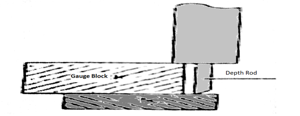
Depth measurement
- Determine the Gauge block sizes required to obtain Caliper indication at approximately 25%, 50%, 75% and 100% of full scale range.
- Clean the gauge blocks using alcohol and lint free cloth. Similarly clean the surface of granite surface plate using Alcohol and lint free cloth.
- Zero the caliper after pushing the jaws together.
- Place the caliper beam base on the first gauge block and move the depth rod to the reference plane. Ensure that caliper is perpendicular to the gauge block
- Record indication of the Depth dimension scale. The caliper must indicate the Gauge block size within the permissible tolerance limits.
- Repeat step “d” to “e” for remaining gauge blocks.