
This guide explains how to verify Coordinate Measuring Machines (CMMs) following the principles and procedures of ISO 10360‑2. The focus is on length verification (E‑test) and probing verification (P‑test) for tactile/contact probing systems.
Coordinate Measuring Machines (CMMs) play a key role in precision inspection. Before diving into ISO 10360-2 verification, you may want to read our Comprehensive Guide to CMMs for an overview of CMM principles and operation.
Purpose of Verification
- Demonstrates traceability to national and international standards.
- Provides confidence in the accuracy of CMM measurements.
- Identifies the health of the machine, guiding preventive maintenance.
- Ensures compliance with OEM specifications and regulatory requirements.
E&R Test
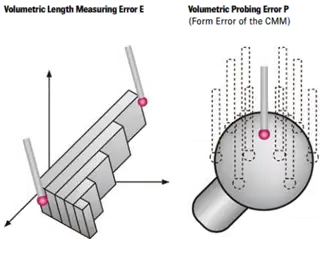
The E&R test involves two types of measurement errors. Volumetric length measuring error E, it applies to all measurements of distances, diameters, and positional tolerances. Volumetric Probing Error P, it applies to all Form measurements of straightness, flatness, Cylindricity, roundness and free form tolerances.
Definitions
- EL(Error of Length Measurement): It is the absolute difference between an indicated length (measured) and the calibrated length (true) length of the artefact.
- EMPE,L (Maximum Permissible Error of length): It is defined as the extreme value of the error of indication of a CMM for size measurement, permitted by specifications, regulations etc. It is measured in one of the following ways:
- EL,MPE = ± minimum of (A + L/K) and B
- EL, MPE = ± (A + L/K)
- EL, MPE = ± B
where,
A is a positive constant, expressed in micrometers and supplied by the manufacturer.
K is a dimensionless positive constant supplied by the manufacturer.
L is the measured size, in millimeters; and
B is the maximum permissible error
- PFTU (Probing, Form, Tactile, Unique): The difference between the measured radii for a single stylus measurements.
- PFTU,MPE (Volumetric Probing Error P): It is the maximum permissible error for probing a reference sphere. It is measured as the difference between maximum and minimum radius of the reference sphere.
PFTU = rmax – rmin
where,
rmax is the maximum radius measured on the reference sphere
rmin is the minimum radius measured on the reference sphere
- Artefact: It is the reference standard used for the verification tests. Various types of artifacts are available for verification and re-verification, and interim check tests, some of them are:
- Step Gauge
- Length bar
- Ball Plate
- Hole Plate
- Purpose made test piece

Preliminary Setup
Below are some of the pre-requisites for performing the E&R test:
- CMM must be operated in accordance with the procedure stated in the instruction manual including machine start up, probe qualification and probe configuration.
- Manufacturer supplied test sphere must be used.
- The environmental conditions must be within the specified limits (commonly 20 °C ±2 °C and RH <90%).
- Cleaning of stylus tip, artefact, machine and gauge blocks.
- Thermal stability of the probing system as per OEM specifications must be ensured
Steps for performing the E test
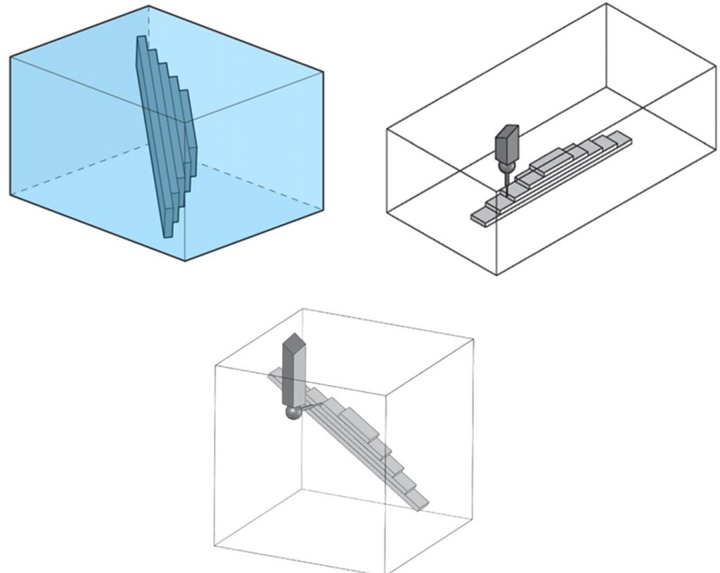
The test is performed to ascertain the volumetric length measurement error E of the CMM. Calibrated gauge blocks can be used to perform the test. For the E test a set of 5 length gauges is measured three times in 7 spatial positions. Total number of measurements: 3 x 5 x 7 = 105. The purpose is to reveal any errors in the measurement volume of the test.
- Mount the gauge blocks in the OEM provided test fixture.
- Select the lengths to be measured along with the speed, approach direction and dwell time of the probe.
- Take the 105 readings in various directions. The seven spatial positions are:
- Along x-axis
- Along y-axis
- Along z-axis
- Along s-partial 1 (Diagonal in XY)
- Along s-partial 2 (Diagonal in YZ)
- Along s-partial 3 (Diagonal in XZ)
- Along s-partial 4 (Diagonal in XYZ)
- Record the measured length and compute the absolute error. EL = Lindicated – LTrue
- Plot results and compare each EL with EL,MPE. 100% of results must be within limits for acceptance, subject to measurement uncertainty considerations.
Sample Calculation
- Manufacturer values: A = 2 µm, K = 1000 (example only).
- For a measured length L = 100 mm the manufacturer formula gives:
- [ EL,MPE = 2 + (100/1000) = 2 + 0.1 = 2.1 µm ]
- Suppose one measured indicated length for that gauge is 100.0019 mm while the true length is 100.0000 mm. Error = |100.0019 − 100.0000| mm = 0.0019 mm = 1.9 µm → this is ≤ 2.1 µm → pass for this measurement.
Note: This example is hypothetical to illustrate calculation. In practice use manufacturer‑provided A, K, B values and full uncertainty budgets.
Steps for performing P test
The test is performed to ascertain the probing error of the CMMs. The probing error is a positive constant, the value of which is supplied by the CMM manufacturer. Here are some of the guidelines for the test procedure:
- The test sphere should be between 10 mm and 50 mm diameter.
- The test sphere should be mounted rigidly to overcome errors due to bending of the mounting stem.
- Twenty-five points are measured and recorded.
- It is a requirement that the points are approximately evenly distributed over at least a hemisphere of the test sphere.
- one point on the pole (defined by the direction of the stylus shaft) of the test sphere;
- four points (equally spaced) 22.5° below the pole;
- eight points (equally spaced) 45° below the pole and rotated 22.5° relative to the previous group;
- four points (equally spaced) 67.5° below the pole and rotated 22.5° relative to the previous group; and
- eight points (equally spaced) 90° below the pole (i.e., on the equator) and rotated 22.5° relative to the previous group.

- If the range rmax – rmin of the twenty-five radial distances (PFTU) is no greater than the manufacturer‘s stated value of PFTU, MPE when taking into account the measurement uncertainty, then the performance of the probing system is verified.
Sample Calculation
- Calibrated sphere true radius: 25.000000 mm (for illustration).
- Measured radii (sample subset) in µm relative to true radius: [−0.6, −0.2, 0.1, 0.8, 0.9, …].
- Suppose rmax = +0.9 µm and rmin = −0.6 µm → PFTU = 1.5 µm.
- Manufacturer PFTU,MPE = 2.5 µm → pass (after considering uncertainty margins).
Measurement Uncertainty
When comparing measured errors to MPEs, always take measurement uncertainty into account. In practice:
1. Determine the calibration uncertainty of the artefact (from calibration certificate).
2. Estimate Type A (statistical) uncertainty from repeated measurements where applicable.
3. Combine uncertainties (root‑sum‑square).
4. Use an appropriate coverage factor (k = 2 is commonly used) to obtain expanded uncertainty.
5. If the measured error plus expanded uncertainty still lies within EL,MPE (or PFTU,MPE), then the result is acceptable.
