Comprehensive Guide to Coordinate Measuring Machines (CMMs)
Table of Contents
Table of Contents
What is a CMM?
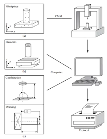
CMMs are modern machines with robust mechanical and electronic architecture used for accurate and precise measurements. These machines work on the principles of taking measurements based on a Cartesian Coordinate System.
The primary job of these machines is to measure actual shape, and compare against desired shape, and evaluate metrological information (size, form, location, orientation). CMMs have the capacity to measure complex geometrical tolerances and deviations on manufactured parts.
Applications of CMMs
The CMMs are extensively used in aerospace and automotive sectors where high precision measurements are required.
These machines ensure the parts are build according to the design specifications. CMMs inspect goods worth over £100M annually in the UK alone.
The measurement tasks usually are associated with measurement of GD&T, reverse engineering, precision alignments, and precision assembly.
Importance of Accurate Measurement
How CMMs Work and Types of Probing Systems
Woking elements of CMMs
The structure of CMM involves three linear axes, one on a moving or static bridge and two other linear axes moving perpendicular to each other. These axes allow a contacting stylus tip to move in mutually orthogonal directions to touch an object.
The stylus of tip records the position of each axis during measurement of a single point. The structure also has servo motors, and linear encoders with gratings to measure the points with micrometre accuracy. The whole structure moves on air bearings to avoid any friction during movements.
The CMMs usually require a 5-bar pressurized air for its movement that is circulated in the tubing up to point of air bearings.
There are thermal sensors attached with each axis and with workpiece to accurately measure the environmental temperatures to compensate them during measurements. The coordinates thus measured are corrected for geometric errors, thermal errors and servo errors to accurately measure the best fitted numerical data.
There is robust state of the art electronics of the machines as well that accurately and precisely position the machine in the working envelope of the machine and allow it to move without any hindrance. The compensations after calibration are also performed using the electronic controllers.
The machine bed is made up of granite surface plate and some companies are now offering granite moving axes as well adding to the reliability and robustness of the machines.
There have been many advancements in the software side of the machines as well. The measurements can now be made as per the standard rules of ASME Y14.5, ISO 1101, BS 8888, and others at your convenience. While fitting criterion are also introduced for adjustments on the go.
Types of CMMs
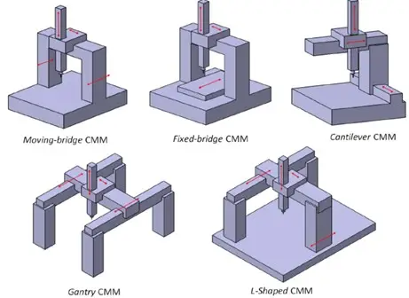
There are various types of CMMs based on the functioning of their moving axes, the types of probing systems and the electronics with which they are operated.
There is the moving bridge type CMMs, horizontal and vertical CMMs, and gantry type CMMs each with their pros and cons.
In the market however, the most common machines are the moving bridge type CMMs. In some countries the classifications are also based on the accuracy, and there is a tight control on import and export of high accuracy machines to countries of concern.
The machines are available in range of sizes, depending on the application you can almost get any size based on your requirements. Some companies even make custom bed sizes to exactly suite the needs of the customers.
Manual CMMs are also available but they are rapidly becoming obsolete and nowadays only Direct Computer Control (DCC) machines are available.
There are limited brand leaders when it comes to manufacturing of these machines. These brand leaders include Hexagon Metrology, Zeiss, Thome, Renishaw, Nikon, UnitMetro, and Mitutoyo.
CMM Probing Systems
Touch Trigger Probes
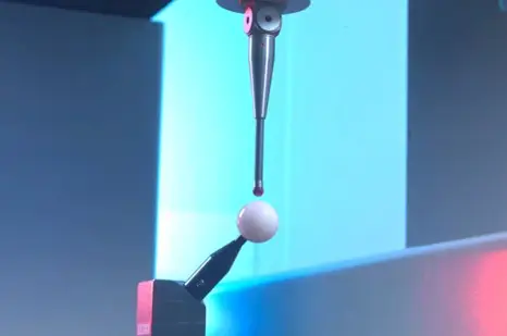
Touch trigger probes are the de facto standard of taking measurements using a CMM. These probes work on the principle of kinematic resistive probing strategy.
The probe rests on three cylindrical rods pressed against pairs of balls to constrain against six degrees of freedom. The probe is triggered when the connection of stylus rods breaks upon physical deflection. The electrical thus generated is read by the electronic encoder system.

Continuous Scanning Probes
The probes have similar designs to touch trigger systems, however, in these probes the data is captured continuously while the probe is in motion.
The famous and most versatile system is of SP600 from Renishaw. It includes Open Loop scanning (for known shapes) and Closed Loop (for undefined, convoluted shapes) scanning.
Non-Contact Probing Systems
With the advent of laser scanning technology, it was inevitable for the CMM manufacturers to include these latest scanners in the CMMs.
The combination of CMMs with laser scanners gives them unprecedented accuracies, because standalone scanners have an accuracy of around 15 µm, when coupled with CMM it is enhanced to the level of the machine itself. There is a range of such scanners available in the market.
Calibration of CMMs
What is Calibration?
It is the process of verification and adjustment of the accuracy of Measuring & Monitoring Equipment (MMEs) by comparing them with standards of known accuracy. It involves compensating errors into the instrument.
Calibration and Verification Standards for CMMs
It is crucial that the accuracy of the machines remain under strict checks.
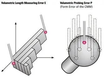
For this purpose Length and Radial Tests (E&R) are recommended to be performed in regular intervals to ensure that the machine continues to perform as per the factor accuracy.
For this, ISO 10360 provides the guidelines to verify the health of the machines.
If the health of the machine is not as per the stated accuracy, laser Interferometry is used to determine the machine errors and then compensated in the machine controller.
Verification Procedures as per ISO 10360
ISO 10360 series of standards detail the acceptance, reverification tests, and interim checks of CMMs.
The tests involve measurement of various lengths of gauge blocks at various positions on the machine bed. Probing error test is usually carried out by measuring the standard artefact for calibration of probing systems at various depths to ascertain the probing errors.
Laser Interferometry Procedure
The geometric errors of the machine are assessed using laser interferometer which is an advanced equipment with accuracies surpassing 0.1 µm.
The geometrical deviations to be measured, include linearity, straightness, rotation, and squareness. Error mapping is done to calculate these 21 geometric deviations, measured and then compensated using software.
CMM Measurement Strategies and Good Practices
General Measurement Strategy
The knowledge of making the measurements right is crucial when it comes to CMMs.
Selection of features, definition of workpiece datum, workpiece orientation, workpiece holding method, stylus system qualification, definition of probing strategy, and CMM programming are some of the areas which need to be focussed when using the machine for the taking the accurate measurements.
Workpiece Setup
The first step is to determine how the workpiece should be placed on the machine bed. The aim should be to measure maximum features in a single setup to minimize operator error.
Consider repositioning methods using reference artefacts for enhanced accuracy. Alignment of critical features along one axis to may help reduce uncertainty.
Defining the Coordinate System (Datum)
The reference coordinate system must be determined as specified on the drawings. These references are known as Datums. Datums are reference surfaces, planes, lines, or points used to define the reference coordinate system.
The most common system is the Cartesian system, requiring a minimum of six contact points to define (three for a plane, two for a line, one for a point). The reference systems must be representative of the features that it needs to measure.
Stylus System Qualification
Probing Strategies
Probing strategies refer to the number and distribution of contact points taken to adequately represent the surface.
Minimum number of points (e.g., 2 for a line, 3 for a circle) are needed by the software to recognize a feature, but more points are used in practice to determine form error (e.g., 5 for a line, 7 for a circle). BS7172 standard recommends minimum points for various features.
Programming the CMM
Data Assessment Methods
When measurements are taken the experienced workers use in-depth knowledge to assess form deviations and measurement errors. They also analyse which fitment algorithms for measurements to use from Least Squares (Gaussian) for average size, enveloping sizes (Tchebyshev) for significant departures from nominal form.
Minimum zone fits for form, inscribing/circumscribing for mating features, and least squares for size/concentricity. These choices significantly affect the measurement results when micrometre accuracy is required.
CMM Software Functionality
Environmental Conditions
Temperature is a dominant uncertainty contribution factor for CMMs. Ideally the measurements must be carried out within a temperature control of 20°±2°.
Cleanliness of workpiece, stylus tip, and work area is essential to prevent inaccurate results and wear. Minimizing vibration by selecting suitable installation sites and isolation measures should be done to minimize the measurement uncertainties.
Operator Skill
Frequently Asked Questions (FAQs)
What is a Coordinate Measuring Machine (CMM)?
A CMM is a precision device that measures the geometry of manufactured parts using a probe that touches or scans the surface. It evaluates dimensions, form, location, and orientation against design specifications using a Cartesian coordinate system.
What industries use CMMs most commonly?
What are the main types of probing systems in CMMs?
- Touch Trigger Probes – capture discrete points on surfaces.
- Continuous Scanning Probes – collect data continuously along a surface.
- Non-Contact Probes – use lasers or optical sensors to scan delicate or freeform surfaces.
How does a CMM achieve such high accuracy?
What standards are used to verify and calibrate CMMs?
How often should a CMM be calibrated?
What is the role of Datums in CMM measurement?
Can CMMs be programmed for automated measurements?
What environmental factors affect CMM performance?
How important is operator skill in CMM inspection?
What is the difference between Manual and Direct Computer Control (DCC) CMMs?
Can CMMs perform reverse engineering?
What software do CMMs typically use?
Why is calibration of the probe stylus important?
CMM Verification
CMM Verification
Understand CMM Verification and how to ensure your coordinate measuring machine performs within specified tolerances.
Learn About CMM VerificationCoordinate Metrology
Coordinate Metrology
Explore Coordinate Metrology — the field focused on measuring 3D geometries using CMMs and advanced metrology tools.
Explore Coordinate MetrologyOur experts can assist you with CMM calibration, verification, and metrology training.