Comprehensive Guide to Mechanical Parts Inspection
Table of Contents
Table of Contents
Importance of Inspection
The design specifications in aerospace and automotive sectors are clearly stipulated in the detailed engineering drawings of various parts and assemblies. These specifications include dimensional and geometric requirements that are the basis of the functional requirements of the products.
The foundations of quality control and inspection processes is built around the concept of making the parts, sub-assemblies and assemblies to perform their intended functions.
Inspections and Product Lifecycle Management

Design and Development
Review of Engineering Drawing including Design for Inspection (DFI), Design for Manufacturing (DFM), and Design for Assembly (DFA). This includes verifying dimensional metrology, tolerances, and GD&T callouts against ASME Y14.5 and BS 8888 standards to ensure inspectability and manufacturability without compromising functional intent.
Procurement
Manufacturing
Inspection of parts vis-a-vis required dimensions, conformance of related certificates and assessments of mechanical and material properties.
Non Destructive Testing Requirements and conformance of allied finishing process including plating, paint and heat treatments. Various ASTM,ISO, and AMS are utilized to carry out inspections during the manufacturing phase.
Acceptance of Assemblies / Sub-Assemblies
Regulatory Inspections
Delivery Inspection
Once the product is ready and all the design requirements and inspection requirements are met, a final check is performed by quality control to ensure that every process has been carried out as per the planned documents.
The product is then formally released for shipment to the customer, in accordance with contractual quality clauses.
Importance of Mechanical Parts Inspection
Having established the role of inspection across the broader product lifecycle, it is now essential to focus on the core subject of mechanical parts inspection.
Mechanical parts are the basic building blocks of any assembly, and their accuracy directly governs the performance, reliability, and safety of the final product.
The system level inspections and testing validate integrated performance whereas parts-level inspections deal with the specific details of geometry, tolerances, surface integrity, and material conformity.
This requires specialized metrology techniques, adherence to international standards such as ASME Y14.5 (GD&T), ISO 1101 (Geometrical Product Specifications), ISO 10360 (CMM performance verification), and ISO 4287 (surface texture parameters), and the application of decision rules defined in ISO 14253 to ensure that parts meet the design intent.
Domains of Inspections
The inspection is a broad field that encompasses knowledge of various domains including Geometrical Dimensioning and Tolerancing (GD&T), material properties, finishing and allied processes including heat treatments, metrological instruments, calibration and documentation requirements as required by international standards.
In the following lines we will outline a comprehensive process typically followed for the execution of inspections within manufacturing industries:
Determining the Requirements of Inspections
The first and foremost thing before commencing inspection of any item is to understand the inspection requirements. This entails an in-depth knowledge of the following:
- Why is inspection required?
- What is to be measured or inspected?
- How is it going to be inspected?
- When it needs to be inspected?
- Who is going to inspect it?
Inspection as stated earlier, is a systematic activity performed to evaluate the quality of parts, sub-assemblies and assemblies, and to determine whether the parts conform to the required specifications.
In this way, inspection forms a critical element of the acceptance procedure, enabling fulfillment of contractual and regulatory obligations at the manufacturer’s end. This establishes the why of inspection.
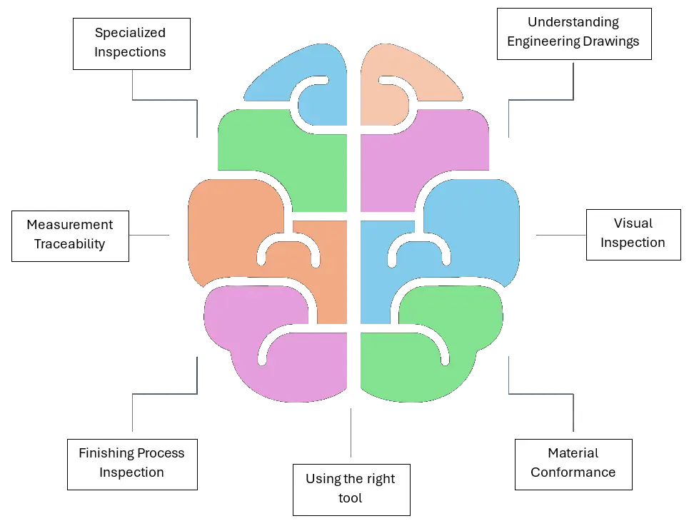
Steps of Mechanical Parts Inspection
Understanding of Engineering Drawings
The foundation of interpreting design intent is the engineering drawing. In Computer Integrated Manufacturing (CIM) environments, usually the design intent is mentioned in the related IGES, STEP or STP file and critical dimensions are digitally designated that are required to be measured.
The latest ASME Y14.5 and ISO 1101 standards outline the rules for digital designation of dimensions, enabling seamless transmission of design data throughout the manufacturing value chain.
Irrespective of the medium, the design intent is communicated down the stream using Geometric Product Specifications (GPS) standards.
The understanding of these standards is essential, as selection of tools and methodologies of measurements directly depend on this comprehension. Once clarity is achieved on what needs to be measured, the process advances to the next stage.
Visual Inspection
The basic step in mechanical parts inspection is to assess the visual condition of the part. It should visually conform to the engineering drawing.
The quantity of a specific line item should be as per the procurement documents and the part must not depict any visual defects.
The visual defects include burrs, sharp edges, extra material, physically damaged part, scratches on the surface, welded material, casting defects, rolling defects, surface roughness not as per requirement.
Assessing Material Conformance
Before starting dimensional inspection, it is necessary to assess the material conformance of the parts. It is usually done by checking the attached material conformance certificates of OEM, or some inspection setups get the parts checked for the material through accredited material testing laboratories.
This requires knowledge of properties of materials and what to see in a material certificate. If it is a structural component that has to bear load, mechanical properties certificate or tests are also required to conform the material to the specifications.
Using the right tool
Rule of 10
The selection of the appropriate tool for measurement is of paramount importance. There are hundreds of tools available for inspection and measurement and there is always a correct tool to measure every dimension.
A widely accepted guideline for selecting the tool is the rule of 10. The tool should be 10 times more accurate than the tolerance of the dimension that is to be measured. For example, if there is a tolerance of ±0.2 mm on a shaft diameter, the tool must be 0.02 mm accurate. In this case, it could be a digital vernier calliper.
For the measurement of GD&T features CMM is usually preferred, for the measurement of diameters bore gauges and pin gauges are used.
Calibration Status of Tool
Equally critical is to consider the status calibration of the tools that are being used.
Calibration refers to the verification of a measurement equipment on planned intervals to ensure that the tool is measuring within the specified accuracy limits.
Usually, the calibration is carried out by ISO 17025 certified calibration laboratories with higher accuracy standards. Prior to use check the calibration sticker on the instrument to assess whether it is within the calibration schedule.
Inspection Environment
The environment of measurement is very crucial for measurements taken by Quality Control Professionals because the dimensional conformity is directly linked with the temperature at which the measurement is being taken.
ISO 1 specifies the standard measurement temperature to be 20° and humidity at 40% – 60% RH (ISO 17025). Deviations from these conditions may invalidate the inspection results.
Verifying of Tool Health
After checking the accuracy and environment, the next step is to verify whether the instrument has any zero errors or any other issues.
For example, in case of vernier callipers it should be seen that the jaws of callipers are perpendicular to the main scale and in the close condition the jaws meet at 0° with one another and they are not off centre. These checks of integrity help verify the health of the measuring instrument.
Precautions during Inspections
Finally, the measurement execution requires meticulous care to protect the item to be measured and the instrument with which the measurement is being taken. In case of measurements taken through CMMs, mentioning correct dwell times for probes is necessary to avoid any collisions.
When handling parts on optical measuring instruments, care should be taken to avoid damage to the stage glass. The inspector should be aware of the various errors that might nullify the measured results like parallax error, sine and cosine errors, thermal expansions, and temperature compensations etc.
Training of Inspectors
Finishing Process Inspection
After the dimensional inspection parts are released for the finishing process that includes any surface protection process including plating, or heat treatments.
After this process final inspection is carried out that considers the visual conformance and adherence of the process to the specified requirements. This is accomplished using certificates and visual assessments.
Measurement Traceability
Once the measurement is taken, the next part is to make a record of the measurements taken.
Usually, the inspection is carried out on sampling basis and sampling standards such as MIL-STD-105, ANSI/ASQ Z1.4 & Z1.9, and ISO 2859.
The sampled values are carefully taken and written down / digitally recorded in an inspection record sheet.
The values are often averaged and entered in the record sheet. This record sheet must contain the following according to the ISO 17020: Inspection Bodies standard:
- Inspection Record ID
- Date of inspection
- Credentials of Inspection performed by
- Place of inspection
- Inspected item identification number with appropriate revision
- Measurement Environmental Conditions
- Sampling standard utilized for the inspection procedure
- Dimensions along with the tolerances inspected / measured
- Tools used for taking the measurements including their calibration ID
- Measurement Results
- Inspection review signatures
This information is stored against the record ID and is traceable to the measured item. Usually, QC stamp / traceability helps retain the record in the archives.
For various reasons this record can be used in the future, for example, the record might be recalled in case of any failure, or during process and performance audits of the organization.
Specialized Inspections
The inspectors need to verify a broad range of parameters for various types of inspections they undertake. This forms the Body of Knowledge (BoK) that the inspectors must possess to appropriately address the inspection issues.
There are some special types of inspections as well that require the inspectors to understand the reasons for inspection in a specific domain for example the inspections of Wind Tunnel Models, assembly inspections of various products, geometric conformance inspections, testing inspections including thermal, humidity, and vibration tests.
These subjects will be expanded further in our next series of articles.
Frequently Asked Questions (FAQs)
Why is inspection important in manufacturing?
Inspection ensures that mechanical parts conform to design specifications, reducing defects, preventing failures, and building customer trust in reliable products.
At what stages of the product lifecycle is inspection carried out?
Inspections occur during design & development, procurement, manufacturing, assembly acceptance, regulatory checks, and final delivery, ensuring quality at every stage.
What standards are most commonly used in mechanical parts inspection?
What is meant by “Design for Inspection (DFI)”?
What is visual inspection, and what defects can it detect?
How is material conformance verified?
What is the “Rule of 10” in inspection?
Why is calibration of measuring tools necessary?
How does the inspection environment affect measurement results?
What are common errors during inspection?
What precautions should inspectors take during measurement?
Why is inspector training important?
What is measurement traceability?
What sampling standards are used in inspection?
What are specialized inspections in aerospace and automotive?
Dimensional Metrology
Dimensional Metrology
Explore Dimensional Metrology — the science of measuring physical dimensions with accuracy and traceability.
Learn More About Dimensional MetrologySurface Finishing Inspection
Surface Finishing Inspection
Learn how to perform and evaluate Surface Finishing Inspections for roughness, texture, and coating quality.
Explore Surface Inspection